


 20-21 / 568

Mechanical properties of printed ABS & it’s relation
to the structure & defects in the printed material
Introduction
The main goal of this research is to discover the relation between the mechanical properties
of the printed ABS to the defects in the printed material by the printing parameters and
building orientations and building strategy.
The strength of FFF printed ABS is composed of at least four components – The welding
strength between printed layers, the welding strength between the wires in each layer, the
wires’ strength and the cavities created during the printing process. In order to improve the
understanding of designing products with mechanical requirements before printing for
preventing failures.
Experimental Method
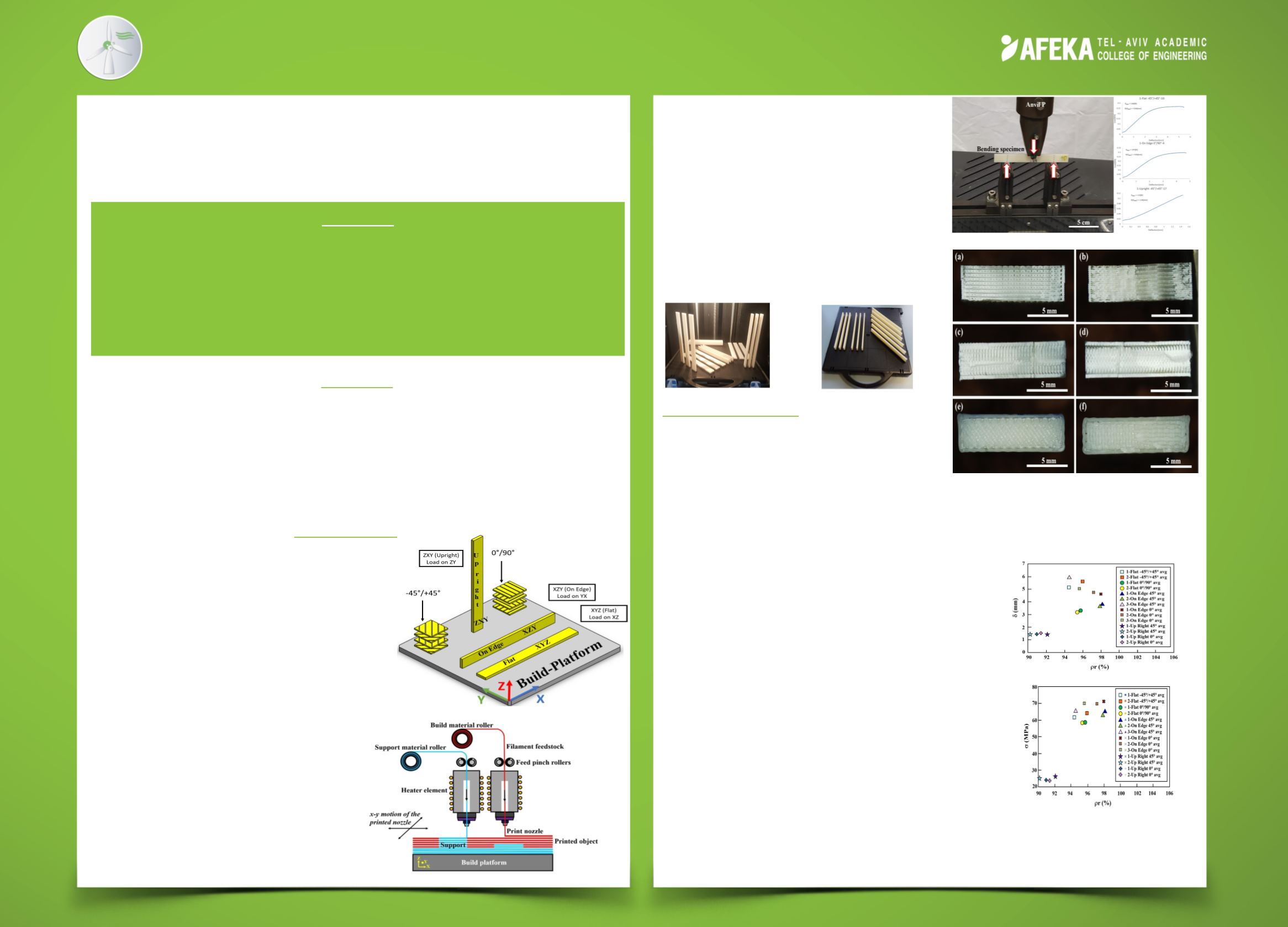
For this study, three-points bending specimens were
printed according to ASTM D790 at the dimension of
3.2(mm)X12.7(mm)X127(mm) using a Stratasys
Dimension Elite FFF printer which located at ‘Afeka’
College (printing process described at Fig .2).
Samples of different building strategy and building
angle were printed and given different names
simplified according to ASTM ISO ASTM 52921 (Fig.1).
Each sample was measured for geometric dimensions
and for mass, then absolute density was calculated,
then divided by 1.04 (gr/cc) (the ABS density which provided
by ‘Stratasys’) in order to calculate relative
density. After the nondestructive test, the
samples were then bent at bending
machine of ‘MTS’ Exceed Model E43 for
axial deflection and strength.
Then flexural strength was calculated.
Fractography analysis was conducted to
the fractured samples.
Or Gewelber
Advisor: Professor Adin Stern
Mechanical Engineering
The first two trays are identical and each of them
has eighteen three-point bending flexural test
ABS specimens that were 3D-printed at six
different orientations (Fig. 3). Twelfth three-point
bending flexural test ABS specimens were
3D-printed in the third tray at two orientaions:
Each of these groups were divided to two:
(1) specimens that were bent next to the build
platform, and (2) specimens were bent far from
the build platform, With the purpose to examine
if there is a change of the mechanical propeties
because of the build platform heating gradient.
Results and conclusions
Based on the three point bending testing results,
it was found that the specimen with the highest
amount of flexural strength is not necessarily the
one with the highest deflection. It was also
observed that On Edge 0°/+90° orientations
shown relatively larger flexural strength difference
in comparison to other building orientations
(Flat and Upright).
Relative density measurements were measured
from mass and geometry tests and then compared
with the manufacture. Average Upright samples
were with the range of 88.67÷92.09[%] against
Flat and On Edge sample that were with average
of 94.41÷98.1[%].
When Comparing deflection between different
groups of the same orientation comes the
realization that there is no dominance to any
orientation, which can be explained by the uneven melting
of the fibers permitting the option of uneven deflection and
structural defects that cause longer movement.
tray’s three data correlate to the data of the first two trays,
while regarding the side of bending, lack of trend appears ,
so it can be said that it doesn’t matter to bend at the area
of creation of the sample or at the area of the ending of
the creation.
From the fractography there is a lack of overlap between
the contour to the interior, that is an area without
melting that cause many defects.
Abstract
One of the main Additive Manufacturing (AM) technologies
is the Fused Filament Fabrication (FFF), in which layers of
molten wires of thermoplastic polymers are extruded in
order to form 3D objects. Mechanical properties and defects
can be changed by different building orientations.
Figure 1
Figure 2
Figure 3
Figure 4
(a)
(b)
Figure 7:ABS 3D-printed three-point
bending experimental results of the Flat,
On Edge and Upright configurations:
(a) density vs. deflection; and (b) density
vs. flexural strength
Figure 6: The fracture surfaces of the ABS printed
specimens after the three-points bending tests:
(a) 1-Flat 0°/90° -2 specimen; (b) 1-Flat -45°/+45° -10
specimen; (c) 1-On Edge -45°/+45° -12 specimen; (d)
1- On Edge 0°/90° -4 specimen; (e)1-Upright -45°/-
45°-17;(f)1Upright 0°/90°-14
Figure 5